
TL;DR (Quick Summary):
The OSI (Open Systems Interconnection) model is a 7-layer framework created by ISO in 1984 to explain how data travels between devices over a network. Moving from bottom to top, the 7 layers are Layer 1: Physical (cables and raw bits), Layer 2: Data Link (MAC addresses and frames), Layer 3: Network (IP addresses and routing), Layer 4: Transport (TCP/UDP and reliable data delivery), Layer 5: Session (managing connections), Layer 6: Presentation (encryption and formatting), and Layer 7: Application (user protocols like HTTP and DNS).
Networking looks hard at first. Too many terms. Too many devices. Too many protocols. The OSI model fixes this problem. It breaks network communication into 7 simple layers. Each layer has one job. This makes learning easy.
In this guide, you will learn what the OSI model is, why it exists, and what each of the 7 layers does. You will also see real examples.
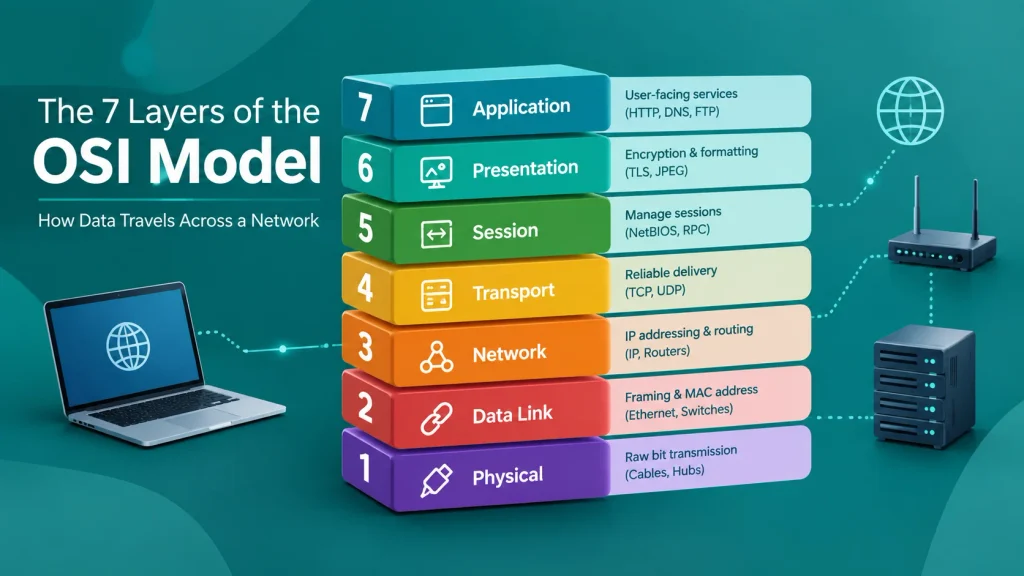
7 Layers of OSI Model
| Layer | Name | Main Work | Example Protocol/Device |
|---|---|---|---|
| 7 | Application | User-facing services | HTTP, DNS, FTP |
| 6 | Presentation | Encryption, formatting | TLS, JPEG |
| 5 | Session | Manage sessions | NetBIOS, RPC |
| 4 | Transport | Reliable delivery | TCP, UDP |
| 3 | Network | IP addressing, routing | IP, Routers |
| 2 | Data Link | Framing, MAC address | Ethernet, Switches |
| 1 | Physical | Raw bit transmission | Cables, Hubs |
Learn more about the physical devices used in these layers with our beginner’s guide to Computer Networking Hardware Devices.
What is the Open Systems Interconnection (OSI) Model?
The OSI (Open Systems Interconnection) model is a framework. It explains how data moves from one computer to another computer over a network.
The International Organization for Standardization (ISO) created this model. ISO introduced it in 1984. Before OSI, different companies used different networking systems. These systems could not talk to each other. OSI fixed this problem. It gave the industry one common structure.
The OSI model has 7 layers. Each layer handles one specific task in data communication. Data starts at the top layer (Application) on the sender’s side. It moves down through each layer. At the bottom (Physical layer), it travels as raw signals through cables or air. On the receiver’s side, the process reverses. Data moves up from Physical to Application.
Here is why the OSI model matters:
- It gives network engineers a common language.
- It helps split a large, complex problem into 7 small problems.
- It helps in finding and fixing network issues fast.
- It helps new protocols fit into the network without breaking old systems.
Note: The modern internet does not run directly on the OSI model. It runs on the TCP/IP model, which has only 4 layers. But the OSI model is still the best way to learn and explain how networks work. Most textbooks, certification exams (like CompTIA Network+ and CCNA), and job interviews still use OSI terms.
What Are the 7 Layers of the OSI Model Structure?
The OSI model has 7 layers. Each layer sits on top of another layer. Data passes through all 7 layers when it travels from one device to another.
Here are the 7 layers of OSI Model, from top to bottom:
- Layer 7 – Application
- Layer 6 – Presentation
- Layer 5 – Session
- Layer 4 – Transport
- Layer 3 – Network
- Layer 2 – Data Link
- Layer 1 – Physical
Students often use a simple trick to remember this order. This trick is called a mnemonic.
- Top to bottom (7 to 1): “All People Seem To Need Data Processing”
- Bottom to top (1 to 7): “Please Do Not Throw Sausage Pizza Away”
You can group these 7 layers into two simple parts:
- Upper layers (5, 6, 7): These layers deal with software and the user. They handle how the data looks and how apps use it.
- Lower layers (1, 2, 3, 4): These layers deal with how data actually moves across the network, from one device to another.
Each layer talks only to the layer right above it and the layer right below it. This is called encapsulation. As data moves down the layers on the sender’s side, each layer adds its own header (extra information). On the receiver’s side, each layer removes its own header. This process is called de-encapsulation.
What Does Each Layer of the OSI Model Do?
Now let’s look at each layer one by one. We start from Layer 1 because that is where actual data transmission begins.
Layer 1: Physical Layer (Raw Signals & Cables)
The Physical layer is the base of the OSI model. It handles the actual hardware. This layer sends raw bits (0s and 1s) as electrical signals, light signals, or radio waves. It does not understand what the data means. It just moves bits from one point to another.
Main functions of the Physical layer:
- Defines cable types, like Ethernet cables and fiber optic cables.
- Defines connector types, like RJ45 ports.
- Sets voltage levels and signal timing.
- Handles data transmission speed (bit rate).
- Manages network topology (bus, star, ring, mesh).
Devices at this layer:
- Hubs
- Network cables
- Repeaters
- Network Interface Cards (NICs)
Real example: When you plug an Ethernet cable into your laptop, the Physical layer sends and receives electrical signals through that cable. Wi-Fi also works at this layer, but it uses radio waves instead of cables.
Layer 2: Data Link Layer (Framing & Error Detection)
The Data Link layer takes raw bits from the Physical layer and organizes them into frames. A frame is a structured chunk of data.
This layer also checks for errors. If a frame gets damaged during transmission, this layer can detect the mistake.
Key responsibilities of the Data Link layer:
- Creates and reads frames.
- Uses MAC (Media Access Control) addresses to identify devices on a local network.
- Detects transmission errors using methods like CRC (Cyclic Redundancy Check).
- Controls how devices share the same network line (this is called media access control).
This Data Link layer has two sub-layers:
- LLC (Logical Link Control): Manages flow control and error checking.
- MAC (Media Access Control): Manages how devices access the shared network medium.
Devices and protocols at this layer:
- Switches
- Bridges
- Ethernet
- Wi-Fi (802.11)
- PPP (Point-to-Point Protocol)
Real example: When your laptop sends data to a printer on the same office network, a switch uses MAC addresses (from Layer 2) to send that data to the correct device.
Layer 3: Network Layer (IP Addressing & Routing)
The Network layer moves data between different networks. This is the layer where IP addresses matter the most. This layer decides the best path for data to travel from source to destination. This process is called routing.
Core tasks of the Network layer:
- Assigns and reads IP addresses (IPv4 and IPv6).
- Finds the best route for data using routing protocols.
- Breaks large data into smaller pieces, called packets.
- Handles traffic between different networks (like your home network and a website’s server).
Devices and protocols at this layer:
- Routers
- IP (Internet Protocol)
- ICMP (used for tools like ping)
- OSPF, BGP (routing protocols)
Real example: When you visit a website, your router uses IP addressing and routing (Layer 3) to send your request across the internet to the correct web server, even if that server is in another country.
Layer 4: Transport Layer (Reliability & Segmentation)
The Transport layer manages end-to-end communication between two devices. It makes sure data arrives completely and in the correct order.
This layer breaks data into segments. It also decides if the connection needs to be reliable or fast.
Primary functions of the Transport layer:
- Splits data into segments.
- Adds port numbers so data goes to the correct application.
- Controls the speed of data flow (flow control).
- Checks for lost data and resends it (only in TCP).
Two main protocols work here:
- TCP (Transmission Control Protocol): Reliable but slower. It checks that all data arrives correctly. Used for web browsing, email, and file transfer.
- UDP (User Datagram Protocol): Fast but not fully reliable. Used for video calls, live streaming, and online gaming, where speed matters more than perfection.
Real example: When you download a file, TCP (Layer 4) makes sure every single piece of that file arrives, and it re-sends any lost piece. When you are on a video call, UDP is used instead, so the call keeps moving smoothly even if a few tiny packets get dropped.
Layer 5: Session Layer (Managing Communication Sessions)
The Session layer opens, manages, and closes a connection (called a session) between two devices.
Think of a session like a phone call. The Session layer starts the call, keeps it active while you talk, and ends the call when you are done.
Key roles of the Session layer:
- Starts and ends sessions between two devices.
- Keeps the session active during data transfer.
- Manages synchronization, so if a connection drops, it can resume from the last saved point instead of starting over.
- Handles dialogue control (who sends data and when).
Protocols and technologies at this layer:
- NetBIOS
- RPC (Remote Procedure Call)
- Session management in APIs and web applications (like login sessions)
Real example: When you log in to your Google account and it keeps you logged in while you check your email, that ongoing connection is managed with the help of session-layer concepts.
Layer 6: Presentation Layer (Encryption, Compression & Formatting)
The Presentation layer prepares data so the Application layer can use it. It acts like a translator between the network and the application.
Main responsibilities of the Presentation layer:
- Converts data into a format that both sender and receiver understand.
- Encrypts data for security (like SSL/TLS encryption on websites).
- Decrypts data on the receiving side.
- Compresses data to save bandwidth, then decompresses it.
Formats and standards linked to this layer:
- SSL/TLS (used for HTTPS websites)
- JPEG, PNG, GIF (image formats)
- MP3, MP4 (audio and video formats)
- ASCII, Unicode (text encoding)
Real example: When you open a website that starts with “https,” the Presentation layer (through TLS) encrypts your data. This keeps your password and personal information safe from hackers.
Layer 7: Application Layer (User Protocols & Interfaces)
The Application layer is the layer closest to the user. It is not the actual software app, like your browser. It is the set of protocols that the software uses to communicate over the network.
Core responsibilities of the Application layer:
- Gives network access to end-user applications.
- Handles file transfers, email, and web browsing.
- Manages resource sharing between devices.
- Supports network services like DNS (Domain Name System).
Protocols at this layer:
- HTTP/HTTPS (web browsing)
- FTP (file transfer)
- SMTP, IMAP, POP3 (email)
- DNS (converts website names into IP addresses)
- DHCP (assigns IP addresses to devices)
Real example: When you type a website address in your browser, HTTP or HTTPS (Layer 7) sends your request to the server. This is the layer you interact with directly, even though 6 other layers work quietly behind it.
Frequently Asked Questions
Do firewalls work at one OSI layer?
No. Basic firewalls work at Layer 3 and Layer 4 (checking IP addresses and ports). Modern firewalls, called next-generation firewalls, also inspect data at Layer 7 (application data).
Which OSI layer is the most important?
No single layer is “the most important.” Each layer depends on the layers around it. But Layer 3 (Network) and Layer 4 (Transport) are often discussed the most, since they control addressing and reliable delivery.